Joystick, buttons, audio
If I were to make a functional arcade cabinet, I'd have to do some of the boring stuff too: an arcade cabinet doesn't consist of a processor and video hardware, but also needs to make sound and have a way for the user to control it.
First the buttons and joystick: a video game is a bit boring without
a way to control it, right? For the joystick, I had a nice Alps analog
mini-joystick, of the sort you also see in various modern gamepads. I could
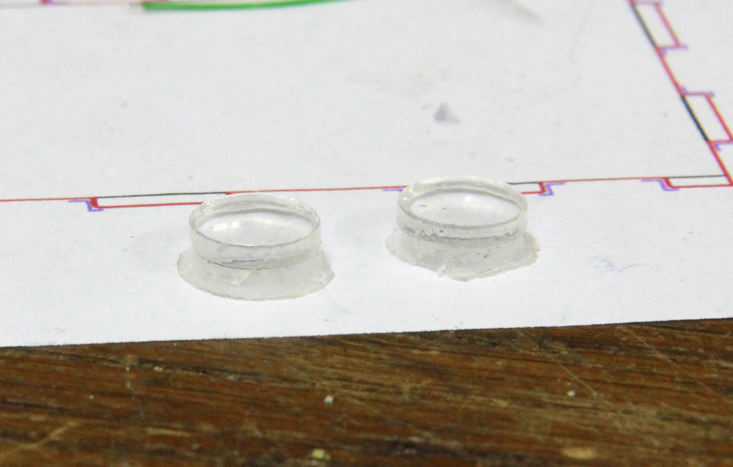
just glue that into the case and be done with it. The buttons needed a bit more
work: they needed to stick out from the casing a bit without falling out when you
hold the case upside-down. I archieved that by gluing a smaller circular
cutout on top of a bigger one and then using a rotary tool to archieve a tapered
effect on the bottom:
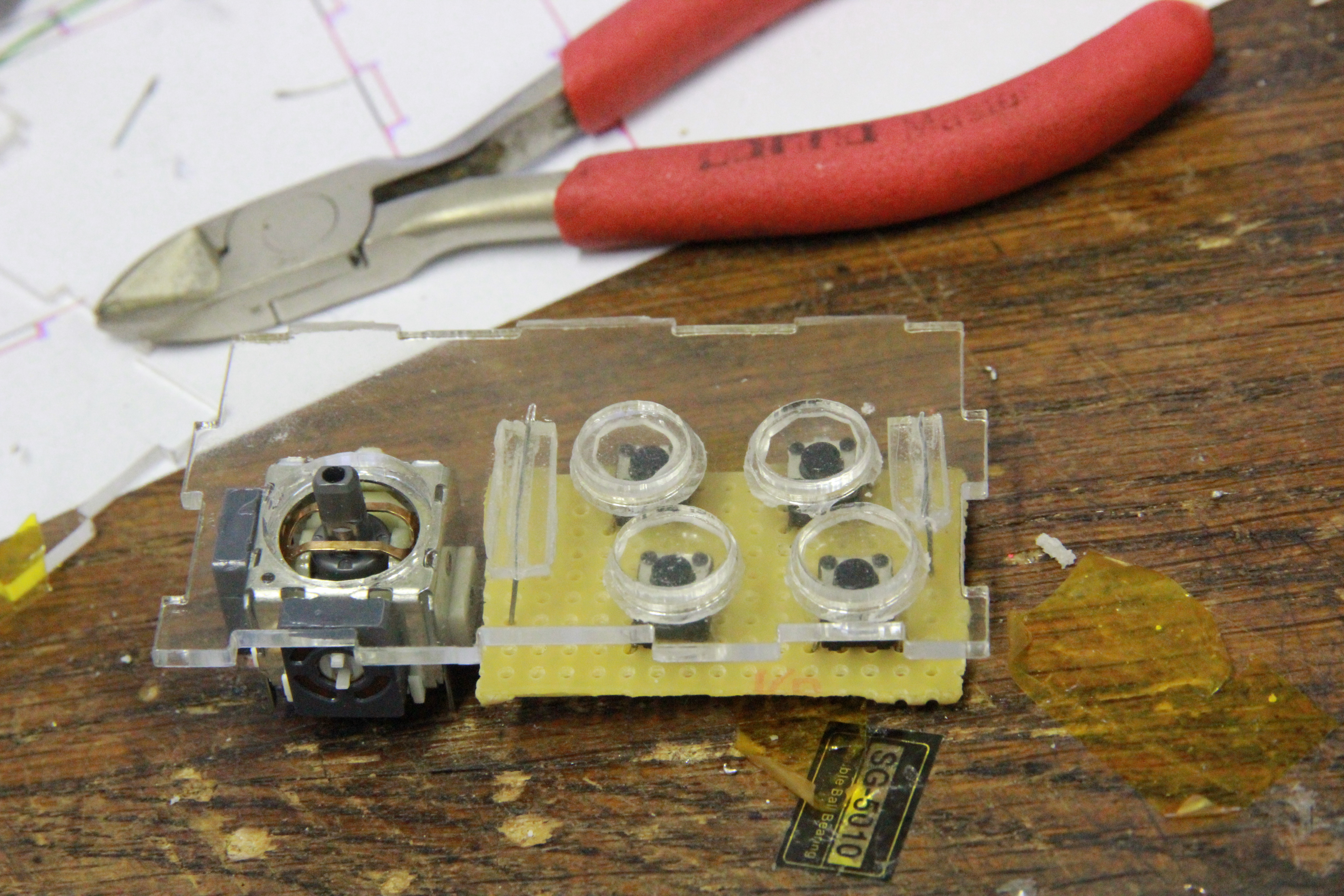
I then soldered some microswitches to a piece of prototyping PCB and used some
wire and some scrap pieces of acrylic glass to hold that in place.
To interface the buttons and analog joystick to the Raspberry Pi, I used M-Joy, which
is a firmware you can burn into an ATMega8 to use it as an USB HID-based joystick.
I didn't have an ATMega8 around, so I used a variant
someone modified for the ATMega88. (Local mirror)
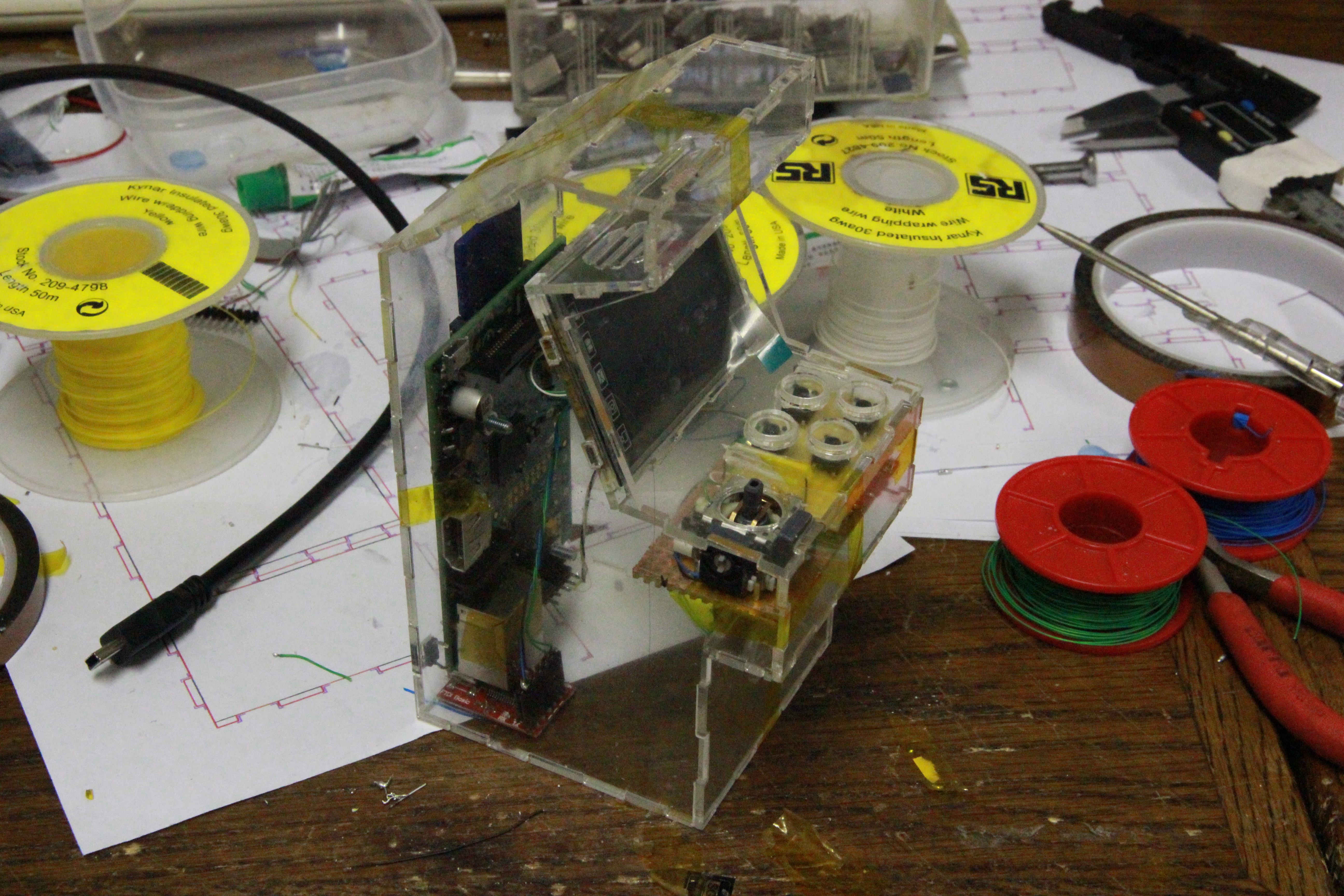
Everything fitted neatly into the space under the buttons:
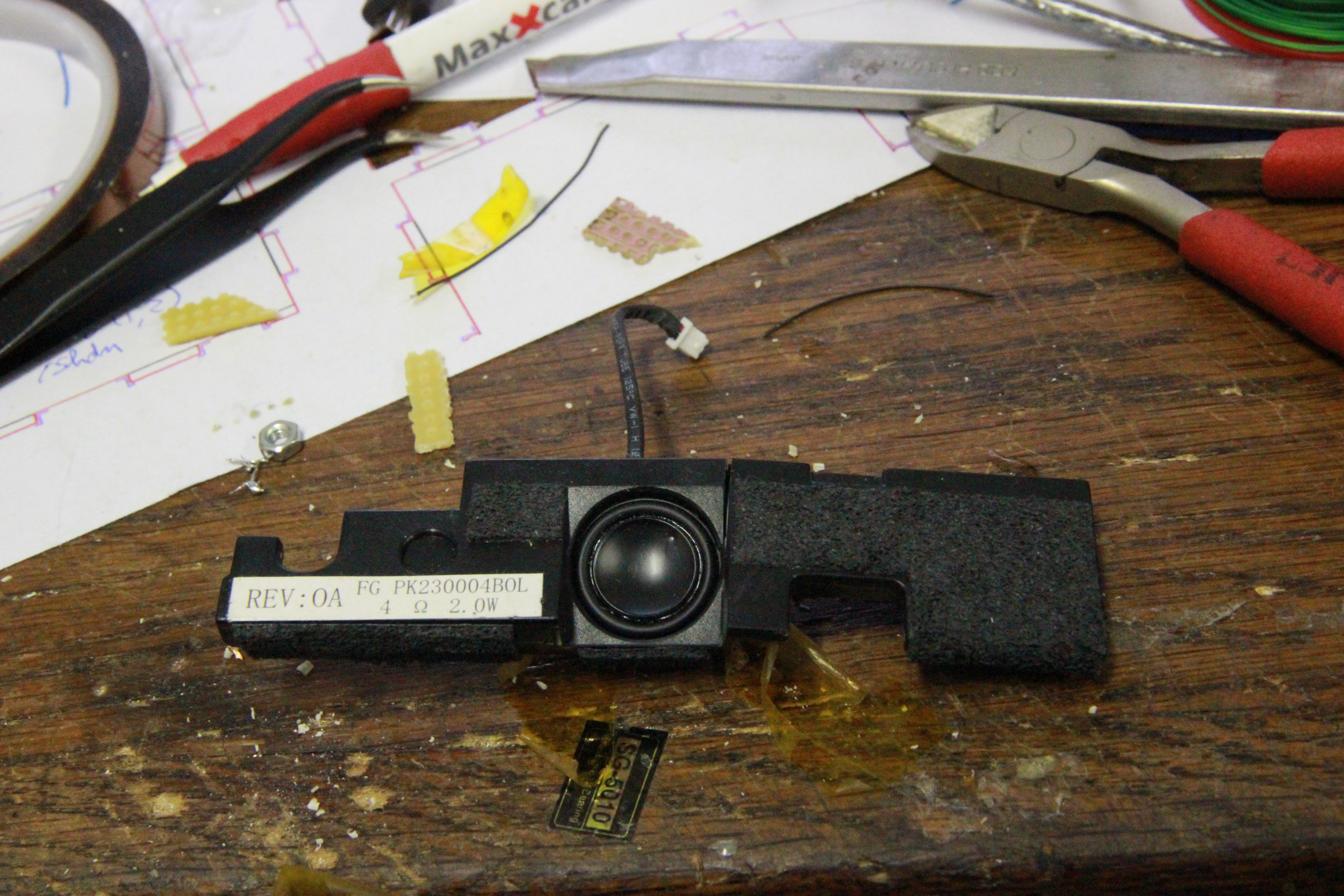
For the audio portion, I decided to use the internal speakers from a broken
Dell laptop. The speakers are a whopping 2 watt and small enough to fit in the
upper part of the arcade cabinet. I got two of them so I could do stereo sound...
not that I'd think there would be much stereo left with the speakers being right
next to eachother, but because it looks right.
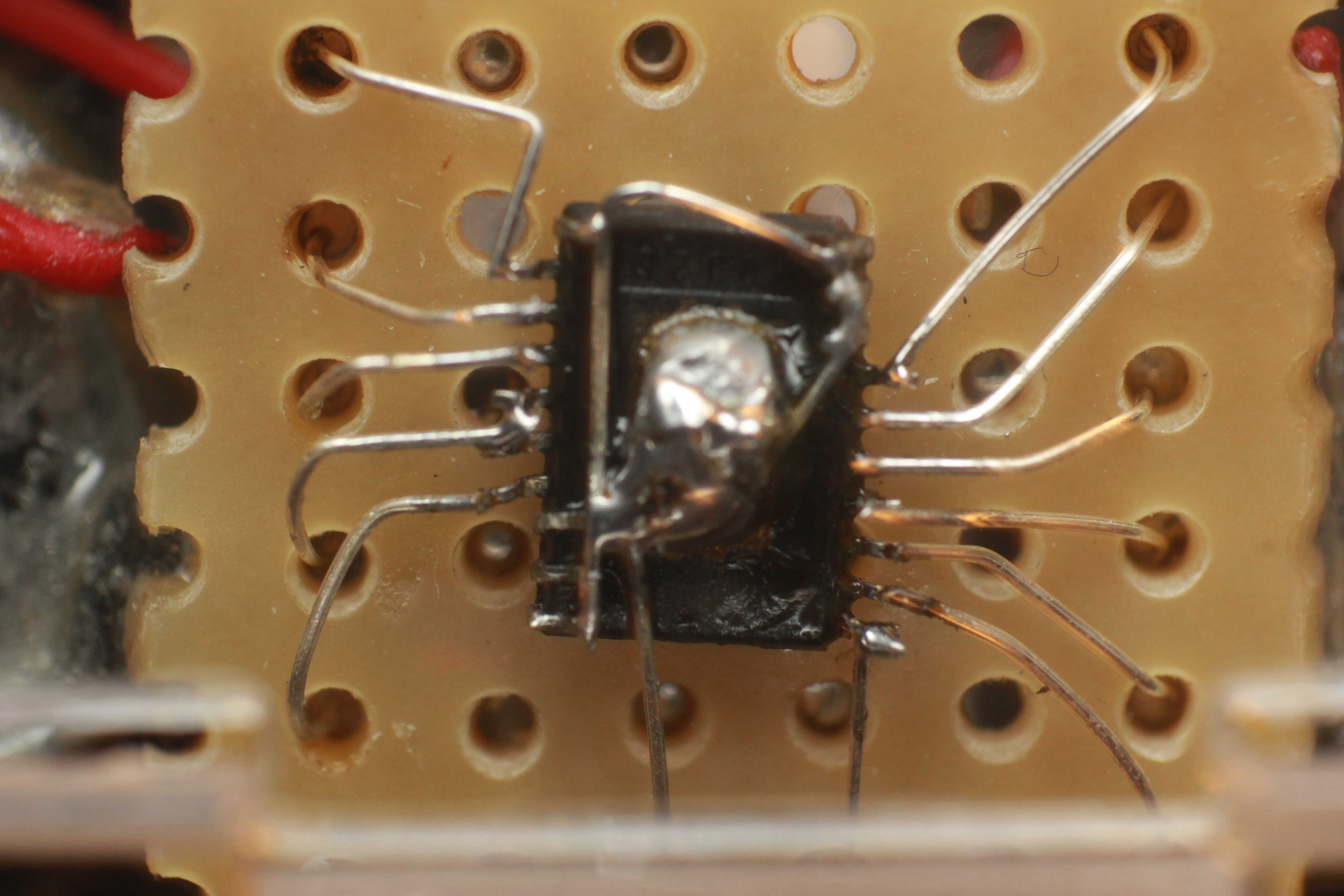
I also needed an amplifier for the two speakers. The original laptop mainboard
had a TI TPA6017 2W amplifier,
housed in a tiny TSSOP package.

This part needs only a few caps as external components, and I could easily desolder
it using a hot-air gun. The disadvantage is that it's
really small, so I decided to dead-bug it on a bit of prototyping board, with the
needed SMD-capacitors on the bottom of the PCB.
I basically followed the reference circuit as shown in the datasheet to build
the amp, so I won't bother you with badly-drawn schematics for it. There's one thing
I couldn't really do, though: the metal pad in the center of the bottom (now top)
should be connected to a ground plane on the PCB, to work as a heat sink. My deadbug
implementation doesn't really have that, so I must be careful not to drive the amp
too hard.
Finally, I glued the speakers in the case and put the amp on top of them. Now my
arcade cabinet had a few watts to announce its presence!
