Power supply
One of the disadvantages of having an arcade machine that small is that it usually doesn't stay in place: the best way to play is to pick it up and hold it in your hands, with two digits controlling the joystick and buttons. The problem with the Raspberry Pi is that it needs 5V, and until now, I've fed it that using the mini-USB-input of the serial-to-USB-converter board. This is less than ideal: the Raspberry Pi isn't specced to run off any USB input voltage and can eat up more power than a USB port is specified to deliver. Plus, having a USB-cable means it can get disconnected, resulting in file system corruption.
I decided to build myself a nice battery powered 5V source. Because I didn't have any battery compartments designed into the arcade cabinet case, I couldn't just throw replacable AA-batteries against the problem... whatever batteries I chose had to remain inside the case while being used and while being recharged. That meant I also had to devise a way to be able to replenish the power as soon as the arcade machine was out of juice.
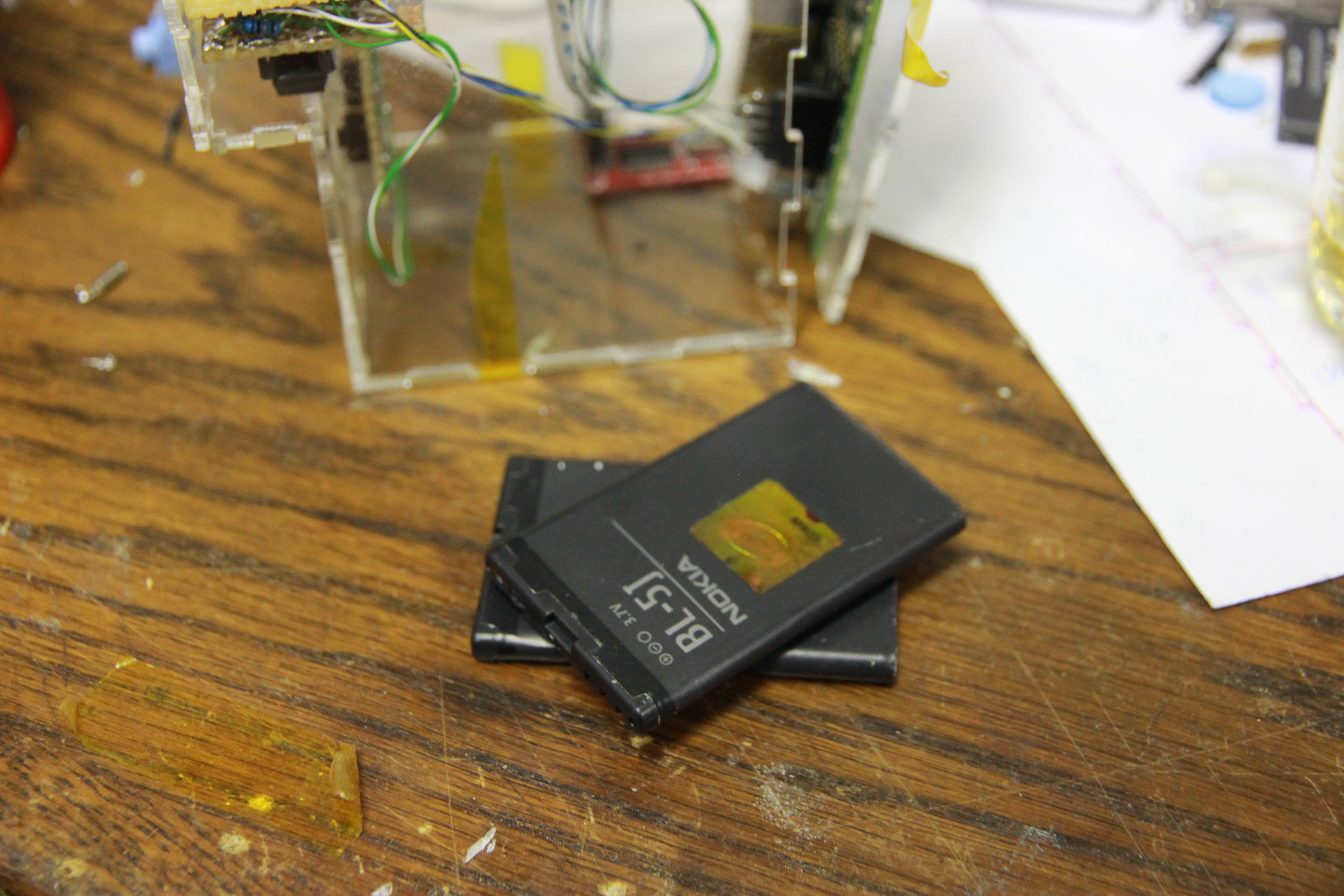
I still had two Nokia BL-5J batteries lying around. They weren't exactly new anymore, but could still hold enough charge to allow the Raspberry Pi to run for a fair while. These batteries also have some protection in them: you shouldn't be able to blow them up by applying too high a voltage or running too much current through them.
That was something I could use, because I was planning on making the charger / 5V PSU myself, with standard components. It would mean a mistake on my side has a much lower risk of blowing up the batteries and causing mishap. If you're going to build this, at least make sure your batteries are protected too. Also, double-check your work. And my schematics and code. Y'know what, if these warnings actually tell you something new, don't build it at all. I'm not responsible for any mess-ups resulting from anything on this page by the way. Also, if you're going to connect LiIons in parallel, make sure they're charged to the same voltage first.
With that being said: here's the schematic:
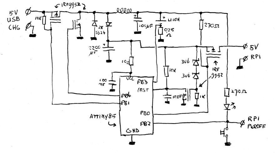
A few notes about the parts: The LiIon is the two Nokia batteries (still with their
protection circuits intact!) in parallel. The diodes are random 2A Schottkys I still
had. The mosfets come as two IRF9952s, which are a N-channel and a P-channel
mosfet in one package. Unfortunately, I have no idea what the specs of the coil are:
I just grabbed one that seemed powerful enough from my parts bin and it seems to do
the trick.
So, how does it work? It's not directly clear from the schematic, because some components and lines are used multiple times over. Basically, the circuit has three modes of operations: idle (off), generating 5V (on) and charging. The idle state is the easiest to explain: the AVR will receive 3.7V from the batteries via the inductor, diode and 10 ohm resistor. It has its IO set to levels where none of the mosfets are conducting, and will try to eat up as little power as possible. Every second, it'll wake up to see if the power button has been pressed or a charger is connected.
If the power button is pressed, the AVR will wake up and start generating and regulating
5V by means of a boost converter.
It'll generate a square wave on PB4, basically letting currents flow like this:
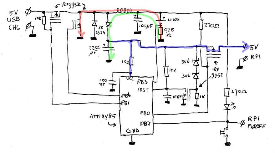
When PB4 is high, the current will run along the red line: from the battery through
the inductor (which will generate a magnetic field) via the mosfet to ground. As soon
as PB4 is made low again, the current will run along the green line: because the magnetic
field collapses, the coil will force a current from the battery through itself and the
schottky diode into the 2200uF capacitor, charging it to a voltage above the battery voltage.
By varying the duty cycle, the AVR
can adjust how quickly the capacitor charges. The AVR itself is powered using this capacitor:
aside from the 10 ohm resistor and 100nF capacitor (which form a low-pass filter, to
filter out spikes) the AVR is almost directly connected with its Vcc-pin to the
capacitor voltage. The ATTiny85 has a way to measure its own supply voltage and uses this
to make sure the voltage remains at 5 volts. As soon as the capacitor is filled enough,
the AVR will also lower PB0, making the connected mosfet convey the 5V to the Raspberry Pi,
which will happily boot.
If, on the other hand, 5V is detected on the USB-port, the device will go into
charging mode. In this mode, it'll charge the LiIon-battery by feeding it 500mA of
current or 4.2V of voltage, whatever is the highest.
The AVR can detect the presence of a charger because the 10K resistor will lead the
5V via the dotted line to PB1. This pin also is one input of the AVRs internal
comparator. The other side of the comparator is connected to Vcc. As soon as the
comparator detects a higher voltage on PB1, it knows a charger is connected and
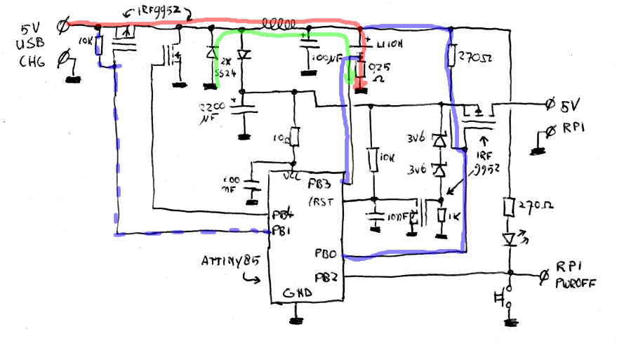
will switch on a square wave on PB1. In this configuration, the device works as a
buck converter,
with the power to the battery coming either from the 5V input (red line) or from
the collapse of the magnetic field in the inductor (green line). The AVR can regulate
the voltage generated by modifying the duty cycle of the square wave on PB1.
To control the generated voltage in a correct way, the AVR will need to measure both the battery voltage and the current through the battery. The current is measured by grabbing the voltage over the 0.25 ohm shunt resistor. The voltage can be measured by AD'ing the value on PB0.
Measuring the battery voltage needs a trick (just as measuring the 5V line does when generating the power for the Raspberry Pi): the reference voltage in the AVR is either 1.1V or 2.56V, which are both too low to measure the 4.2V battery voltage. PB0, however, can be used as a reference voltage, just like Vcc can. If that reference is used to measure the 1.1V internal reference (which can be switched to be an input), it's possible to measure voltages >2.56V without needing external resistor dividers.Two parts of the schematic haven't been explained yet. The first is the part around the 3V6 zener diodes: this is a crowbar-like protection circuit. As soon as a voltage of about 9V is detected on the 5V line (e.g. because of a bug in the code), the mosfet will pull down the reset-line of the AVR, hopefully shutting down whatever process let the voltage get that high. 9V may seem a bit high for a protection voltage, but just one spike has to get that high; the average voltage probably is lower when that happens.
The other part is the bit around the button and LED: this is a combined charge indicator, power switch and soft-power-off. When charging, the AVR will blink the LED, indicating how far the charging process is. When powered on, the Raspberry Pi can detect if the button is pressed for a short while; the AVR will ignore this. When the button is pressed for longer than 4 seconds, however, the AVR will immediately shut down power to the Raspberry Pi. For this to work, the 'RPi poweroff' line should be connected to Raspberri Pi GPIO30, and the 'power' program (included in the download) should run.
This allows for a complete soft-power bootup and shutdown: Press the button once to power on the Raspberry Pi. Go play a game. When done, press the button once more. The Raspberry Pi will detect this and shut down. At the end of this process, it will make the line to PB2 low, simulating a long press of the button; this will cut the power to the Pi again. If something goes wrong, you can manually hold the button for 4 seconds and perform a hard powerdown that way.
All this logic still fits on a small PCB about as big as the batteries it takes care of:
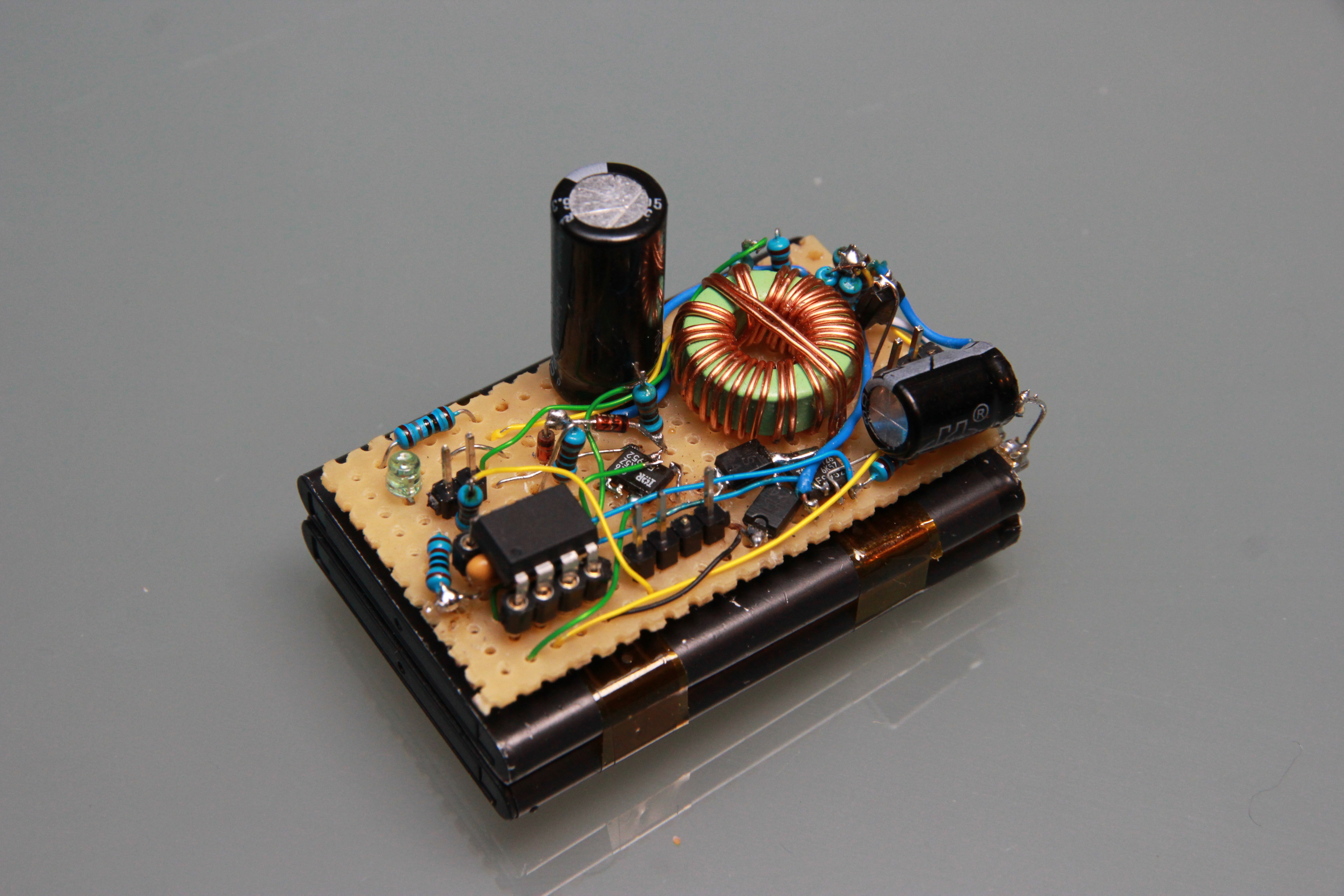
The software for the AVR and the small daemon that watches for button presses and can shutdown the power can be downloaded here.