Design
First of all, I needed to know what I was working with here. Luckily 1943 is an arcade machine that was in widespread use and as such is documented fairly extensively: Mame supports the game and you can download service manuals and even the complete schematics from the Internet. The machine itself is fairly typical for it's time period: it contains two Z80s, one for the audio and one for the game logic, some ROM and RAM and a huge, dedicated circuit for the generation of the graphics. The machine is built almost completely from 74xx logic and ROMs, with just one small dedicated IC at the heart of the GPU and a programmed MCU one used for copy protection.
So, how could I make the game save its scores to something non-volatile? I could ofcourse add an EEPROM somewhere in the Z80s address space and then hack the firmware to load and save the highscore table to that. This would probably work, but the hack then would be restricted to only this type of arcade machine. Making the thing do more ludicrous tricks, like tweeting the current highscore, would be almost impossible: the Z80 would have to talk over TCP/IP as well as run the game, not to mention the NIC I'd have to wire into the existing arcade PCB.
I decided to take an alternative route, which is to add another bus master to the existing Z80 bus. A little explanation may be in order: A CPU like the Z80 has a parallel bus to read and write bytes from and to it's peripherials. This bus consists of 16 lines carrying the 16-bit address to be accessed and 8 lines carrying the data that is read or written. Some more lines indicate what should happen with the data: /RD becomes active if the data should be read from the address, an active /WR means a byte should be written. The Z80 can do accesses to I/O-ports and memory: in the former case /IOREQ is active and in the latter /MREQ will be. Normally, the rest of the hardware will look at these signals plus the top few address lines to see if the access should go to ROM, RAM or something else.
The main memory of the arcade machine has two bus masters; the main Z80 and the graphical hardware, called the GPU from now on. The machine has a third bus master, namely the audio CPU, but it sits on a different bus and doesn't play a role in this project. Normally, the main Z80 will be reading bytes from the ROMs and reading and writing into the RAM. Every now and then, however, the GPU will need to peek into the Z80s RAM to see what it is supposed to display. In order to do this, it'll ask the Z80 to stop accessing memory for a while and will take over the bus in order to get that data.
My idea was to throw a third bus master into the mix: a separate microcontroller that would run a program within its own memory but has access to the Z80s bus. That way, it could tell the Z80 to relinquish control over the memory bus whenever the graphical hardware wasn't doing so, and then access every byte in the Z80s RAM, including the location where it stores the highscores. Saving the highscore would then be easy: just read out the highscore table a few times a second and store it somewhere in an EEPROM. On boot-up, the stored data can be re-written back into RAM. With the separate microcontroller in the mix, adding an Ethernet controller and TCP/IP-connectivity wasn't going to be all that hard either.
With all this in mind, I designed the following schematic: (click to embiggen)
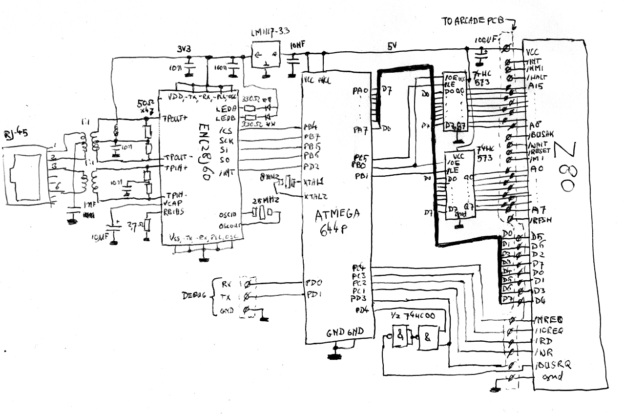
On the right is the original Z80, whose bus I would tap. In the middle, there's the AVR doing the tapping, a fairly hefty ATMega644P. The AVR doesn't have enough pins to access all of the Z80s bus directly, so there are two 8-bit latches to help the AVR send an address to the bus. The /BUSREQ-pin of the Z80 is separated and the signal on it is ORed with a pin on the AVR using a 74HC00. (This looks a bit weird, but remember the /BUSREQ is an active-low signal and it all works out.)
How does this all work? When the graphical hardware (the GPU) wants to take over the bus, it will make the incoming BUSREQ-signal active. The Z80 will finish what it's doing and grant the GPU access to the bus. If the AVR wants to do something on the bus too, it will now also activate its BUSREQ signal. As soon as the GPU indicates it's done with its work, it will deactivate its BUSREQ-signal, but because of the AVRs signal, the Z80 will not take over the bus. Now, the AVR has a chance to read from and write to the bus, by first sending the low and high parts of the address to the latches and then using the /MREQ and /RD or /WR-lines to read or write a byte.
On the left side of the schematic is an ENC28J60, a SPI-controlled Ethernet-chip. It's connected to the AVR in a fairly standard fashion, and provides the TCP/IP connectivity mentioned before.