Schematic
...when I would run into a nice VFD like this:

This is a 11-digit VFD with 13 segments per digit, so it can display letters
and numbers just fine. The downside is that it does have an input per digit as well
as one per grid, totalling at 24 inputs. That'd mean soldering 48 transistors and
96 resistors for the level-converters needed alone! While I can be quite productive
when it comes to projects, I am somewhat lazy too: I didn't feel like soldering
at least 336 pins, so I tossed it aside.
Recently, because of a topic on a Dutch forum, I re-thought the whole VFD-business,
picked up my VFD and started measuring its specs. It still seemed to work and
used about 3V for the filament. Applying 15V to the grids and segments manually
even made it light up:
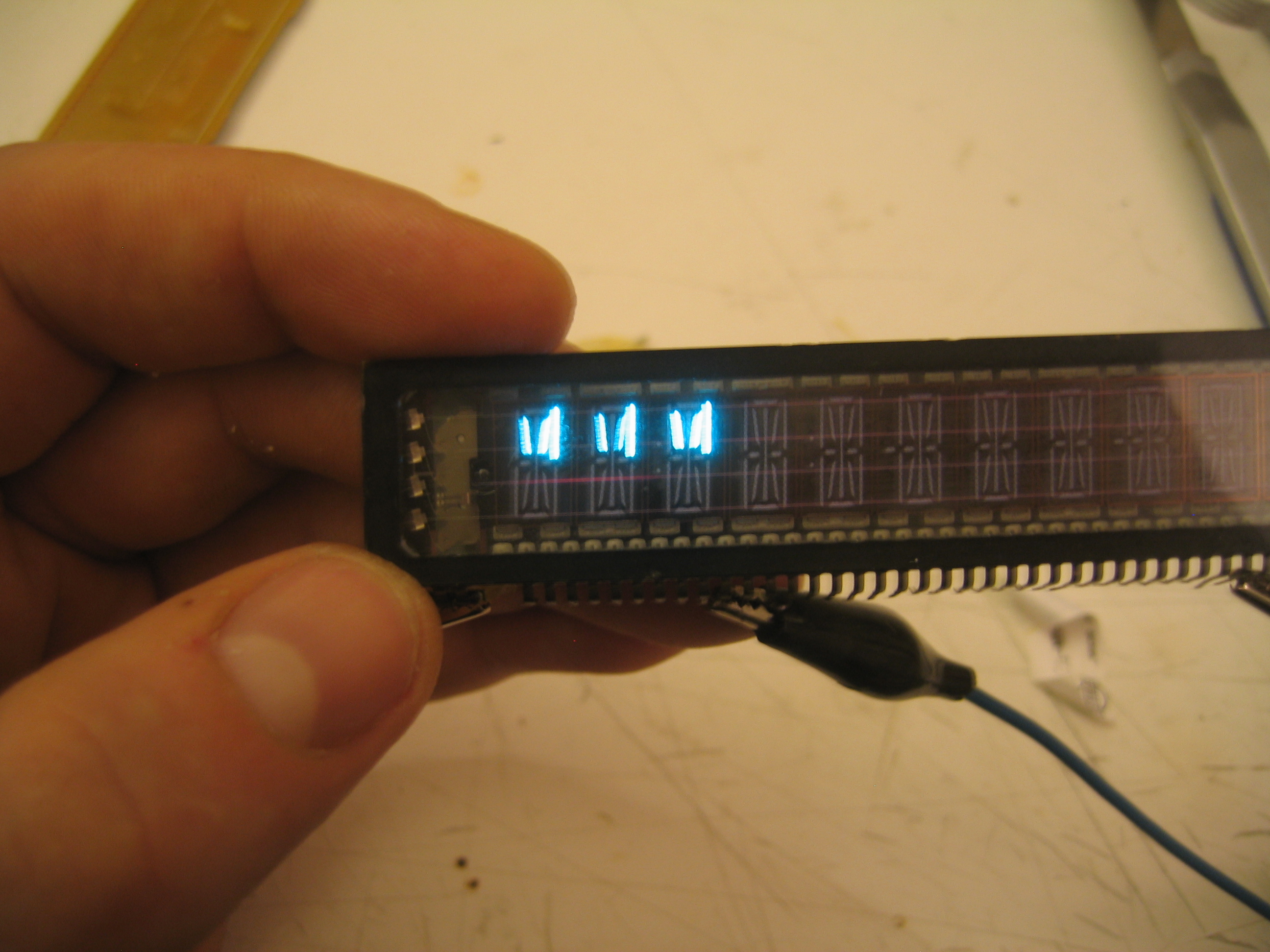
In this configuration, the grids and segments used at most 2mA per input.
These measurements made me think again: 15V @ 2mA should be switchable in an easier way than just using 5V logic and analog level-converters. Ofcourse, if I wanted to get the VFD just working, I could order a VFD-controller from e.g. Maxim but that'd be like cheating for something theoretically as simple as this problem.
After a while of pondering, I remembered I had worked with non-5V logic before:
the ancient 40xx-series of logic, in contrary to the more popular 74xx-chips, can run
off a power-supply from 5V up to a whopping 15V. I quickly checked the datasheets
and the idea seemed feasible: I could use the 4094, which is an 8-stage
serial-in-parallel-out chip to drive the VFD without problems. I ended up with
the following schematic for my VFD-driver:
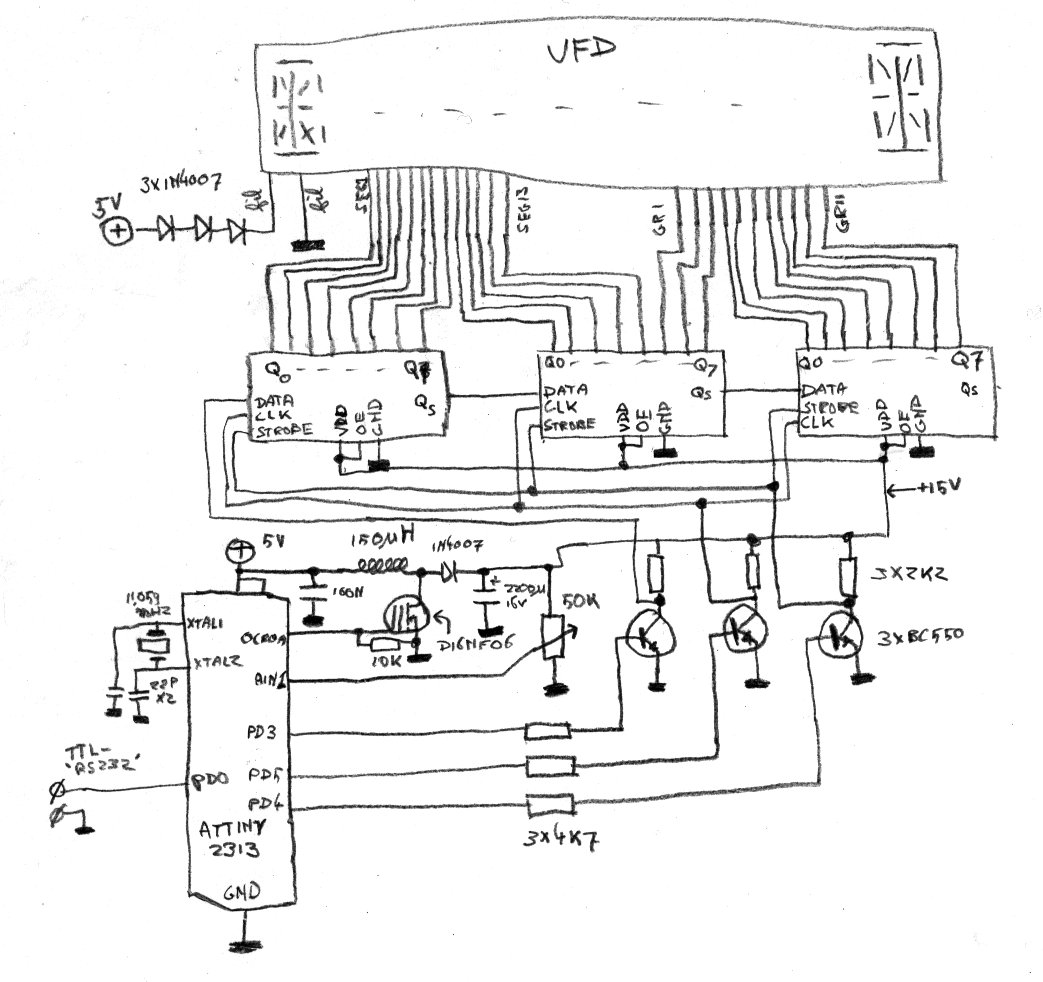
At the top, the VFD is shown. Its filament is driven by about 3V, created by
putting 3 diodes in series with the 5V powersupply. Its inputs are directly driven
by the 4094s without those irritating voltage converters in the middle. The
inputs of the 4094 are driven by three voltage converters to convert the microcontrollers
5V to the required 15V. That 15V is generated by the little boost-converter
connected to OC0A of the AVR, with a feedback loop going to AIN1. The microcontroller
will adjust the 15V the boostconverter outputs so that AIN1 will always have 1.1V
on it, so by adjusting the potentiometer connected to it, the 15V can be adjusted.
On the right of the AVR are the crystal and the serial connection the AVR gets its
data with.