First light
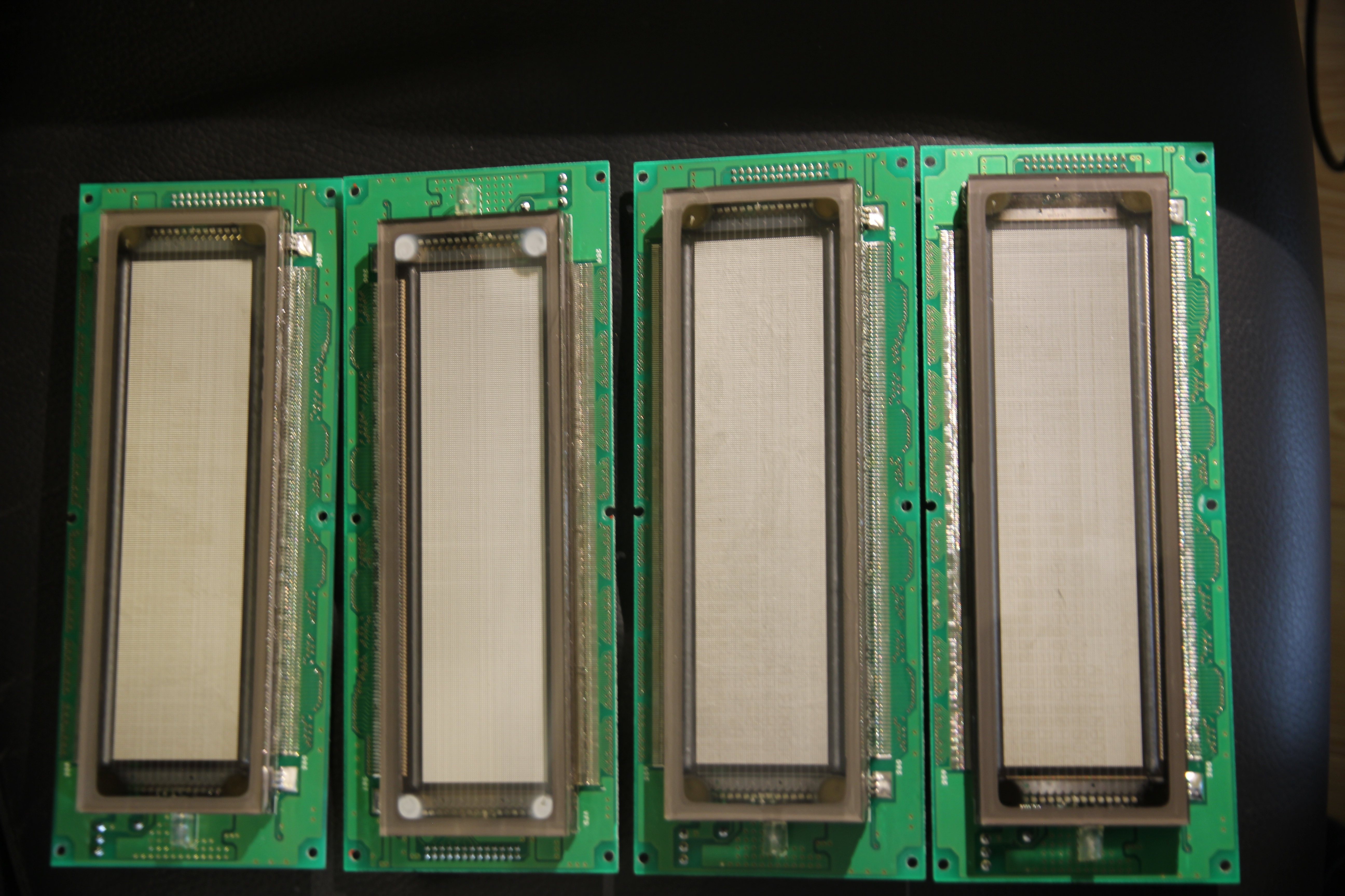
So here are the displays. There is a reason they were only RMB40, however...
 .
.
Three of the four displays have quite a bad case of burn-in: some of the text of the devices they were in is readable, even with the display off. The fourth has no burn in, and for a good reason, which is visible in the picture: the metal blobs in the corners of the display have gone white, These metal blobs are the result of the flashing of so-called 'getters' and are basically metal deposits which can react with the small amounts of air still residing in the VFD enclosure. The ones in the fourth VFD are white instead of metal-colored because they are oxidized by coming into contact with large amounts of oxygen, meaning the vacuum seal in the VFD has been broken sometime in the past, rendering this VFD non-functional.
Fortunately, the other 3 VFDs seemed still OK, apart from the burn-in, but I couldn't be sure of that until I powered them up and let them show something. But how to do that? The typenumber said the displays were of type 'GU256x64-W376'. Entering this into Google gave no results, apart from a few people saying that they had mailed Noritake for a datasheet but got the response that this was a customer-specific product and there were no public datasheets available for it. The closest hit was for a VFD with the product number 'GU256x64-372'. This VFD seemed a good match for the VFD I had, apart from one thing: this VFD was supposed to be fed 5V through pin 3 of its power connector, with pin 1 being the ground. The datasheet said the middle pin was not connected.
For my VFD, ground on pin 1 checked out: that pin was connected to the ground of all the chips. 5 volt on pin 3 was also believable: the pin was connected to the Vcc of several 74-logic chips. Unfortunately, my VFD did nothing with only this connected. That aside, it had the middle pin of the connector connected to a fairly hefty 4A fuse, which is not what I would call 'not connected'. It seems this display needed an extra voltage, but which one? Luckily, some sleuthing quickly figured out a reasonable voltage: the smoothing capacitor on the line was an 10V one, so it would not be more than that. Some reverse engineering also gave me a minimum voltage: one of the chips on the PCB of the VFD was an MB3771 voltage monitor, and the configuration resistors it was connected to told me that chip would detect an undervoltage at 6.2V. This meant a voltage like 6.5V would probably make the thing work.
Now, what data to send to the device? The '372 display I had the datasheet for had a 20-pin
connector with an 8-bit parallel interface to talk to the on-board controller, plus a sync output
and an input to blank the VFD. On my display, it wasn't easy to reverse engineer which line did which
because most of the active lines connected directly to the controller, but the way they did and the way
the grounds were connected made it look very likely the bus structure was the same. Hooking it up to
a Raspberry Pi and dumping commands to it confirmed this: the display came to life and displayed
stuff!
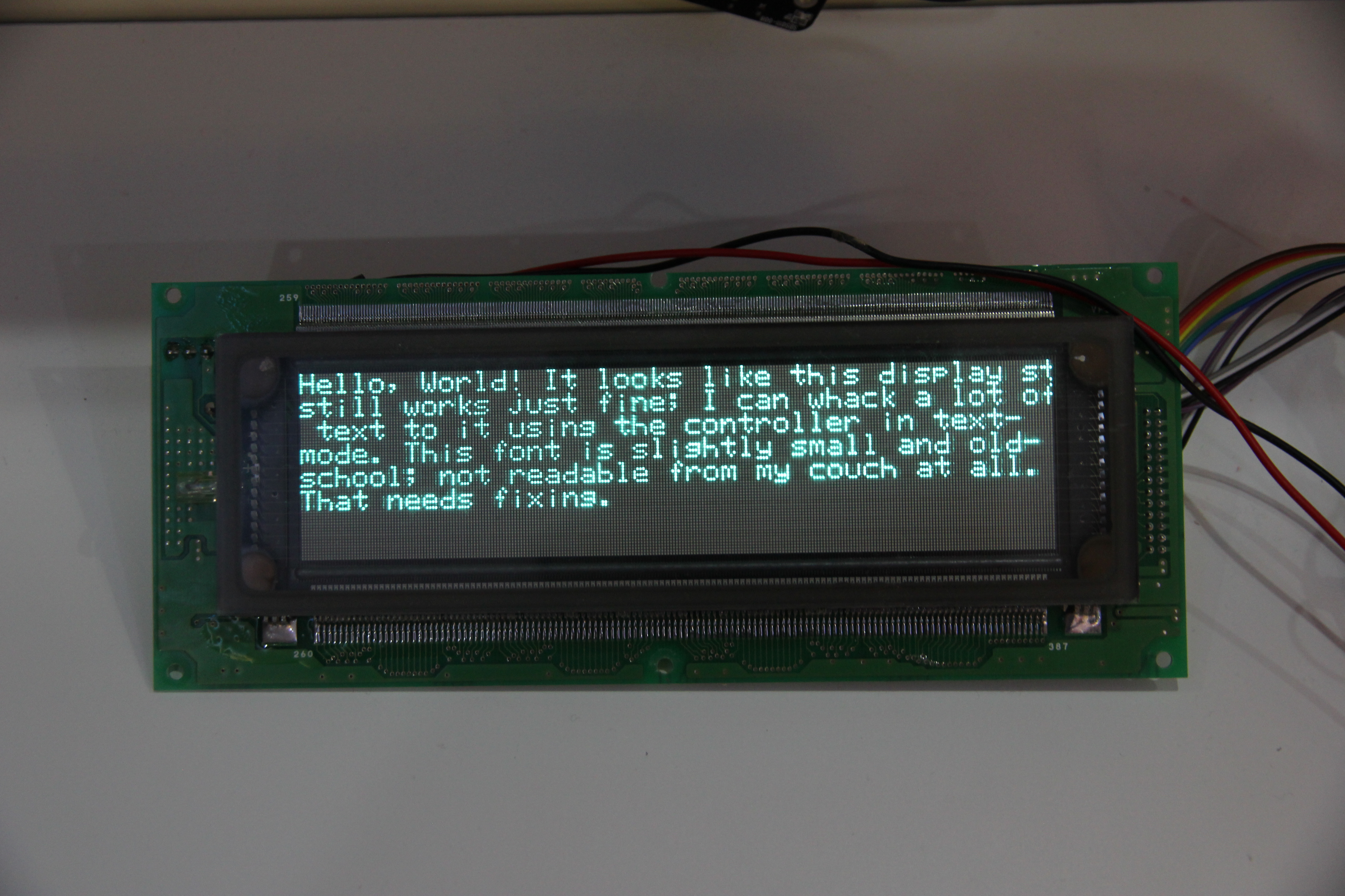
Now, I was planning to use this for a living room display, and the internal font was slightly too small
and, to be honest, a fixed-width font is not really the pinnacle of prettiness. Luckily, the display also
has a graphics mode, and I could use libcairo to quickly whip up an image to send to that:
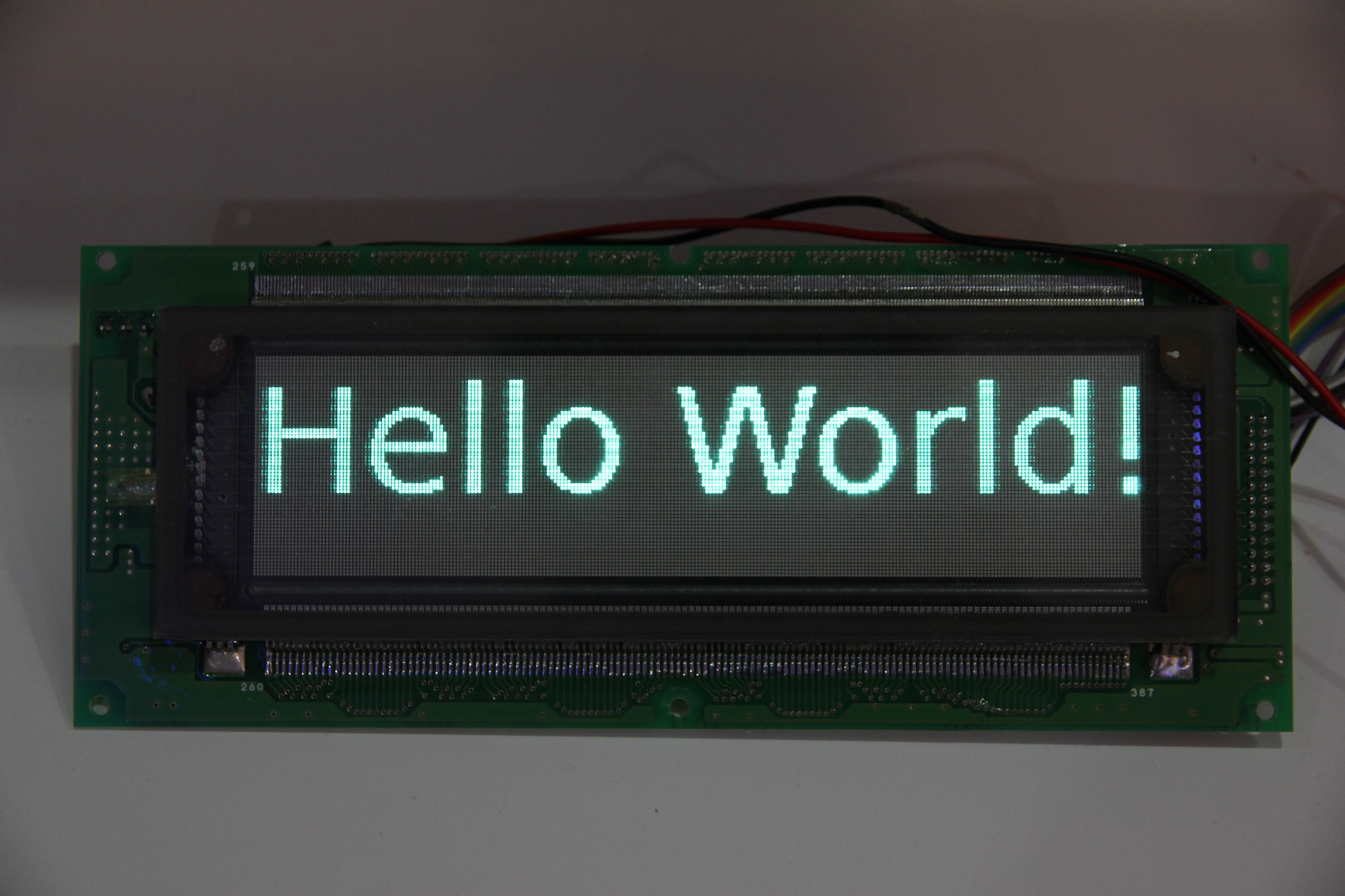
This still had some disadvantages: when I used wiringPi, I could only push around two frames per second to the display. I could probably improve that by skipping the library and doing direct I/O manipulation. There were some other problems, however: the display controller couldn't do grayscale, and the display still had some bad burn-in. This would show up especially on moving images, and my plan was to incorporate a lot of moving graphics in my end result; it would be turned on 24/7 and moving everything around would help a great deal with preventing more burn-in.