New controller
So how do we make a display that can only turn pixels fully on or off, show grayscales? Well, with the controller the display came with, it's impossible: the controller just does not support it.
The controller isn't the only chip on the PCB on the back of the VFD, however. Apart from it and the character ROM and the video RAM it needs, there's a fair amount of other chips there. There's the voltage comparator that kills the VFD when voltages get too low and the boost converter that generates the high voltage for the VFD, but most of the chips actually are uPD16326 chips, which are high-voltage shift registers. Eight of these shift registers are there to select the current column of pixels, while four of them receive the data for two of these columns. These shift registers are the interface between the high-voltage world of the VFD and the 5V-only controller chip and the controller talks to the VFD exclusively through these chips.
This scheme with row and column shift registers is pretty familiar to me: it is also used in dot-matrix LED displays, and I already created a new grayscale-capable controller for a 224x28 LED display. The way I did it back then was by abusing the DMA-engine inside a Raspbery Pi to continuously send the contents of a large range of memory to the GPIO pins in order to generate the signals needed to display an image. There's no reason why I couldn't do the same thing here.
So I dug up the code for the display I made earlier, upgraded it a bit (the fact that I use a Raspberry Pi 2 now, plus the fact that some things changed in the 4.x kernels meant that some things didn't work in the same way as they used to) and I had a working signal generator for the RPis GPIO pins. Now I just had to connect them to the shift registers.
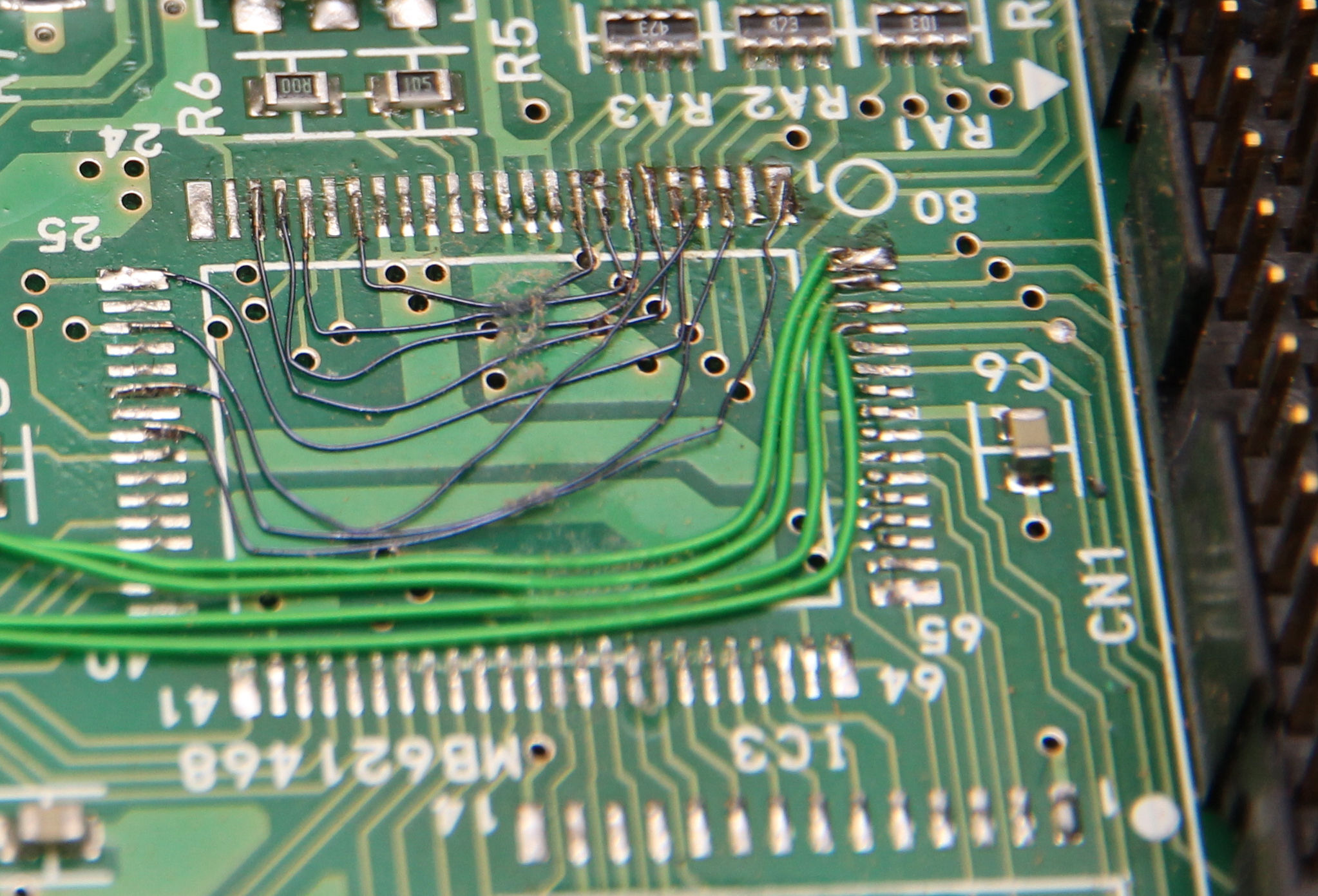
The easiest way to do that was to desolder the controller and replace it with a few bits of wire,
connecting the pins connected to the data connector straight to the pins connected to the shift registers.
This meant I could re-use the existing IDC connector, making the entire thing very sturdy.
The way the original controller controls the 4 shift registers that hold 2 lines of 64 pixels of data, is by putting them all in series and clocking in 128 bits. I decided that speed would probably be an issue later, and I'd be better off disconnecting the series connection and feeding each shift register individually. That way I could feed 4 bits of data every clock pulse instead of just one, theoretically making the interface almost 4 times as efficient.
In theory, the software would be pretty simple: clock a bit into the 256-bit wide row driver so the
first row is activated, clock the corresponding row data into the column registers, wait a moment, shift
the row bit, clock in the next data, etc. Because of the physical peculiarities, the actual scheme is
slightly different: instead of activating a column, you have to activate the two thin vertical wires
left and right of the pixel column you want, meaning the column drivers need to be fed two bits instead
of one. Also, the odd and even columns are driven by separate shift registers, which actually is visible
on the back of the VFD glass:

The reason for this probably is that the vertical wires that select a column are shared between the two pixels neighbouring it, and with all row pixels connected together, the scolumn of pixels left and right of the active column would also light up slightly. In the configuration the VFD has, these columns are instead driven by another row driver IC, which can be disabled to blank out these pixels entirely.
With that figured out, getting data to the VFD became just a case of correctly writing the software.