Theory
The idea I got from looking at my projector was that maybe I could suffice by projecting 2 infrared 'dots' on the wall. Imagine two flashlights, shining at a white wall. If you point a camera to it, the camera has no way to tell if the two dots on the wall are made by flashlights, or if the wall actually emits light itself. The WiiMotes work the same way as the camera: if they see two spots of light coming from the wall, they don't care if the spots came from the sensor bar or if the spots where projected there.
So, what did I need to project two infrared dots on the wall? Two powerful infrared light sources would be nice, plus a lens to get the light projected on the wall. So, let's get things started!
First of all, the infrared light sources. I needed two of them, and I needed them to be quite powerful, so I bought 2 Osram SFH4231s on Ebay. These little critters manage to output 2.2W of IR-light at 940nm, the wavelength at which the WiiMote is purported to work best. They need a steady current of 1A to do this, though.I didn't had a current supply like that on hand, so I needed to create one. I could
have used a LM317 or a huge-ass current limiting series resistor, but I didn't quite
like the idea of wasting power on some kind of linear regulator. So I whipped up a
switched mode current source from a LM2575-ADJ:
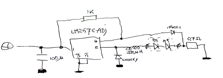
The schematic is basically taken from the datasheet of the chip, with the feedback
circuit as an exception. The idea is that the LM2575 always tries to keep its
ADJ-input (pin 4) at 1.23V: if the voltage there is lower, it'll increase the output
voltage; if it's higher it'll decrease it. Normally, you use a voltage divider to
make sure that at the output voltage you want, the voltage at pin 4 is exactly 1.23V.
I didn't need a constant voltage but a constant current, so I decided to insert a
shunt resistor instead of a voltage divider.
I could have left out the diode plus 1K resistor and made the 0.7 ohm shunt resistor into a 1.23 ohm one. Then, if the current through the leds would be 1A, the voltage over the shunt would be 1.23V and the LM2575 would try hard to stick to that 1A as well as it could. The disadvantage there is that the 1.23 ohm shunt resistor would eat up 1.23W of power, which is a waste. Back to the actual schematic: The diode plus 1K resistor add 0.6V to the voltage over the shunt, so the voltage over the shunt only has to be (1.23-0.6=)0.63V; a 0.63 ohm shunt will do the job and only waste a bit more than half a Watt. I fixed the shunt at 0.7 ohm because that would leave a bit of headroom for the LM2575, which is specced at a max of 1A.