Hardware
So, first of all I needed to build the hardware. I started my design with some requirements. What I wanted is that the picture frame would connect to a server over WiFi once a day to pick up any new images. It would then display one on the Eink display; if it managed to download new images it would show one of those, or an old image if not. It would then go back to sleep for 24 hours. Picking a chip for this was not hard: I happen to work for Espressif, a company which makes great WiFi-enabled microcontrollers that also have a deep sleep mode that works pretty well. I picked an ESP32C3 for this: it is nice and cheap and has all the features I would need.
Furthermore, I also had some requirements for the power supply. I wanted this thing to resemble a normal picture frame as much as possible (aside from the fact that it changed pictures nightly), so any external power supply was out of the question: the power supply had to be some kind of internal battery. I also wanted to ship this thing internationally, so it would be best if it could ship without a battery. That requirement ruled out any kind of rechargable LiIon cell. I settled on using 2 AA batteries; they're available everywhere and even the grandparents would have little issue replacing them if needed.
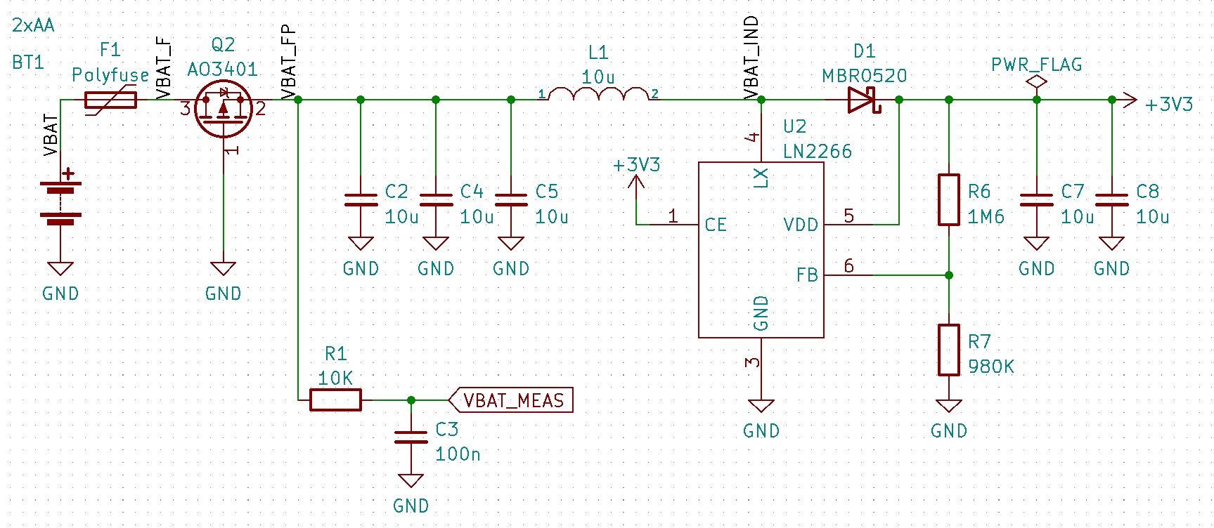
As 2 AA batteries give a total voltage that starts off at 3.2-ish volt, but decreases during their lifetime, I needed a boost circuit to get that up to the 3.3V the E-ink display and the ESP32C3 need. Looking at the discharge graphs here, if I wanted to get the most out of a pair of alkaline batteries, the boost circuit would need to work with an input voltage down to 2.0V or so. Additionally, as the ESP32C3 would need to be properly powered even in deep sleep, the quiescent current would need to be suitably low. With these requirements, I started hunting for a feasible boost converter.
I settled on the Natlinear LN2266. This diminuitive chip is made by a Chinese manufacturer, meaning it's generally a little bit less susceptive to the current silicon shortages. It starts working at 2V, has a no-load current of 56uA and can provide the 500mA or so of WiFi startup current the ESP32C3 needs. I designed it so it pulls its power from the two batteries via a P-channel mosfet that is configured to protect against the batteries being inserted the wrong way around. The battery voltage is also connected via a RC filter to an ADC pin of the ESP32-C3 in order to get an idea of how much juice still is left. I also initially designed a small polyfuse in the design, but that turned out to have too large a voltage drop to work; I replaced it with an 0-ohm resistor in my PCBs and removed it entirely from the design files.

The ESP32-C3 comes in the form of an ESP32-C3-WROOM-02 module. This module contains the WiFi microprocessor plus 4MiB of flash, as well as all the RF components needed including a trace antenna. To program it, I added an internal header where I can solder an USB cable; the internal USB-JTAG-serial converter takes care of the rest. I added an OTA firmware update feature to the firmware (meaning the frame can download new firmware from my server), so if I need to do any updates to units that are already closed up and out in the field, I can do that by pushing the new firmware remotely.

Then there's the E-ink screen. It's connected to the PCB using a flat-flex cable, and it needs some odds and ends to work: a MOSFET, an inductor and some caps and diodes so it can generate the voltages it needs, some decoupling caps and a resistor or two. The E-ink display also has a connection for an external LM75 temperature sensor: I designed one in, just in case, but the firmware doesn't use it as the screen also works well without it.

All of this is placed on a very roomy PCB. As the 'raw' E-ink display is glass and somewhat fragile, I designed the PCB to work as a backing to make the total product less prone to breakage. The PCB is even bigger than that, as the mounting holes, any through-hole components (like the battery contacts) and the WiFi antenna all must be placed outside where the E-ink display is mounted.

Finally, there's the case, which I designed in OpenSCAD. I used some tricks to make it look less bulky: it needs a fair amount of thickness as the AA batteries need to fit and I did not want a large bulge in the bottom, so I used some large chamfers and a slope in the back. Those tend to be hidden if you look at the picture frame from the front, so effectively the overall picture frame looks a lot sleeker. The picture frame also looked a bit bulky compared to the visible area of the E-ink display: in order to fix that I added a mat (also called passe-partout). As the mat is printed in white and contrasts with the black case nicely, it breaks up the 'sea of black' and makes everything look in proportion.
In the back, there's the battery component. It's open-able by unscrewing one screw (as I didn't want to rely on fragile 3d-printed clips to keep it in place) and as the silkscreen of the PCB has the correct battery orientation on it, replacing batteries should be simple.